
Xmods most Frequently Asked Questions
'Tips and Tricks' to tune your Xmod?
Crest Spin Brush (SB) Motor Modification
'Builder's Corner' Reader's rides
'Review Section' Info on parts and vendors
This modification I believe may also be known as 'Tite-Turnz' and uses the same basic principles but locates the parts in a more user friendly area where normal (not to great at soldering) people can install the resistors. Obviously this type of modification could result in a non-functioning Steering Servo or possibly a dead mainboard if you are not careful so tread lightly and only attempt this modification if you feel confident you can solder and follow instructions reasonably.
This will void any warranty you have on your Xmod and if you do screw up your Xmod don't blame me this has worked for myself and many others so you are warned!
Parts and tools required:
- Soldering Iron
- Rosin Core Solder
- Heat Shrink tubing or Electrical Tape
- 3.3k ohm 1/2w 5% Carbon Film Resistors
You will need 2 of the Resistors and you should be able to find them and the other items at any Electrical store or even the local Radio Shack.
Note: If you are new to soldering or just clumsy, try your skills out first and practice until you get the hang of it. There are resources that explain in detail the proper way to solder. Practice soldering points on an old circuit board that you don't need. Remember Heat is the enemy so use a low powered 15 Watt Soldering Iron and always use Rosin Core solder not Acid core as it's not suitable for electronic circuits.
How much will the steering be improved?
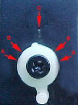 |
If you look to the picture to the left you’ll see the front of an Xmod’s steering servo. The arrow that is in the center of the picture which is marked (C) is the servo’s neutral or start position, the servo normally only travels to the position which is marked (B) after you install the kit the servo will travel to the points marked (A) this gives you about 30-35% reduction in the turning radius. Please note that as far as anyone can figure they limited the travel to avoid issues with using the AWD drive kit because if the servo was allowed to turn fully it may bump or bind against the gear used in the AWD drive kit so if you have the AWD drive kit installed you will need to watch for this issue and you can rectify it by either performing a few trims to the parts involved or use the steering trim on the controller to minimize the travel. |
Ready? lets get started!
- Take your batteries out and put them somewhere else! If your antenna or the wire to it touches the batteries or any power source within the car your range will be fried. This step is a must before attempting any work on your Xmod trust me on this many people have inadvertently fried the receiver because they failed to follow this simple step!
- I'll assume you are familiar enough with your Xmod by now to tear it down far enough to expose the Steering servo but if you need a little help you'll need to basically strip it down to the Chassis by removing the front deck and four screws, two screws beneath the car near the power switch, one screw near the antenna wire on top, the rear deck, and both parts of the motor mount. When you can get to the servo unhindered you can stop.
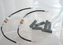
I have seen a kit offered on e-bay that seems like a good idea they basically attached wires to the resistors to make the install easier. These longer flexible extensions allow you to place the resistors anywhere in the chassis and make the task of fitting everything back together much easier as you'll have more options on placement.
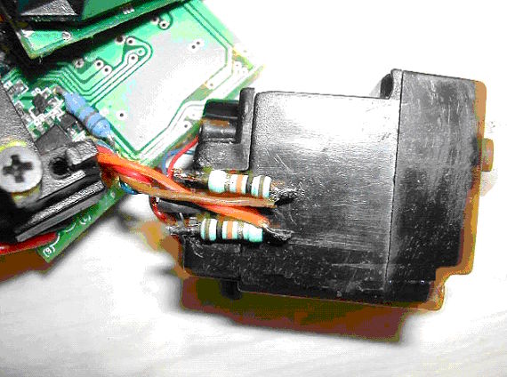
- There are two small wires and three large wires going from the Mainboard to the steering servo, you'll need to cut the large brown one and the large orange one. How and where you decide to cut these wires is up to you one method for installing and positioning the resistors is shown in the photo below.
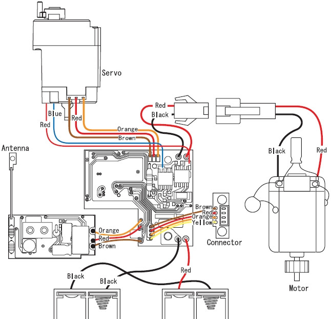
- Here is the wiring diagram for the servo section this should make the task of locating and understanding where those wires go.
- After completing the soldering of the resistors make sure you use the Heat Shrink or Electrical tape to avoid any possible shorts from exposed wires.
- Re-assemble your Xmod making sure everything fits correctly and make any adjustments needed fit everything back together, remember to check for problems if you have the AWD drive kit installed or you install the kit in the future.
I needed to cut a slight bit off the tie-rod in order to create the needed clearence and I will warn you to be careful when handling the servo and boards as the wires are very thin and will break off if bent back and forth a few times I know as I ended up with a servo that would keep trying to make a left turn
until I found the issue.
Have fun and take your time with this one...
biline