Back to R/C Toys
Introduction to Xmods
Xmods most Frequently Asked Questions
'Tips and Tricks' to tune your Xmod?
Xmods Manuals
Crest Spin Brush (SB) Motor Modification
Upgrades for your Xmod
'Builder's Corner' Reader's rides
'Review Section' Info on parts and vendors
'Motor Guide'
Xmod Evo Models
Evo v.s. Xmod
Upgrades for your Xmod Evo
Evo's most Frequently Asked Questions
'PimpMyMod' section

|
|
SB Motor Modification with Isotropic Ferrite Magnets
This Tutorial will also work equally well if you have purchased a set of Neodymium Magnets
This modification is fairly easy to do, I will provide photos and step by step instructions on completing this modification. You will require some tools and a basic knowledge of how to work with your Xmod. I will be doing this without pulling off the pinion gear as this requires a special tool (photo)
You will need:
- Crest Spin Brush or Spin Brush Pro.(photo) for those who have purchased Neodymium Magnets you can obviously skip this part.
- 30 Watt soldering Iron
- Solder wick (photo)
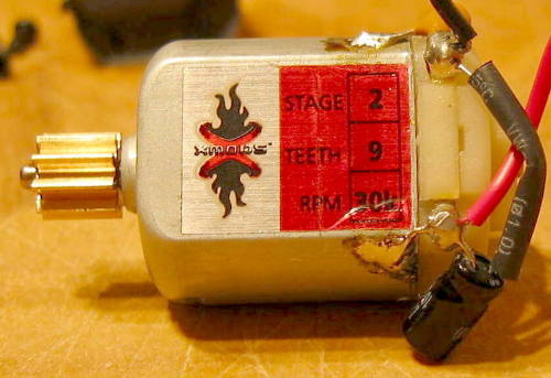
- Radio Shack Stage 2 Motor of your choice
- Small hobby screwdriver set
- Small set of Needle-nose pliers
- Paper clip
- Patience!
For those of you new to soldering or those that just want some good tips click Here in a nutshell these are the basic rules to good soldering.
- Wipe the tip on the sponge.
- 'Tin' the tip with solder.
- Apply the tip to both the component and the board.
- Add solder to the joint (let the solder touch the board and tip).
- Let the solder flow for a second or two.
- Replace soldering iron, the joint should be shiny (not dull).
Use only the recommended soldering iron (25-30 watts), preferably temperature regulated with a small tip. Keep a wet sponge near the soldering iron. KEEP YOUR SOLDERING IRON TIP CLEAN! When it gets dirty (black crud on tip), wipe the tip on the sponge. When you solder, place the iron-tip in contact with the wire /component AND in contact with the printed circuit board (contact both at once).
Another tip: to get the solder to start flowing after cleaning the tip, quickly melt a drop or two of solder onto the tip (called 'tining the tip') and then immediately apply the tip to the board/wire, heat both up and apply solder to the joint. When solder flows smoothly and covers the joint remove the iron. The solder joint should be shiny, not gray and dull (a cold solder joint). This process should not take more than 5 seconds from grabbing the iron to putting it back in the holder. If you apply too much heat to the joint, the heat may damage a component. Practice soldering on an old PC board, try soldering scrap pieces of resistor leads to a terminal on the board until the connection look good. That way you can get a feel for how much heat is needed to get a good solder flow in a minimum period of time.
SB Motor Modification Tutorial
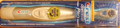
This is a Crest Spinbrush Pro I purchased it new for $11.99 hopefully you can get an old one to destroy and save yourself some money.
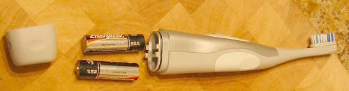
Start by removing the bottom cover and removing the 'AA' batteries (Hey nice bonus you get a set of Energizer's, I did overpay for them).
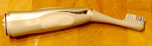
Bend the brush section back until the case starts to pop open now carefully keep cracking the case open until it splits.
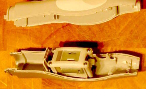
After you remove all the extra stuff from inside the brush you'll be left with the motor sitting by itself attached with 4 small screws, remove these screws to free the motor from the trusty Spin Brush.
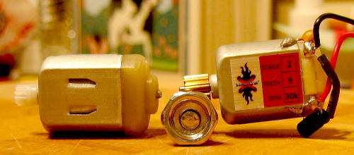
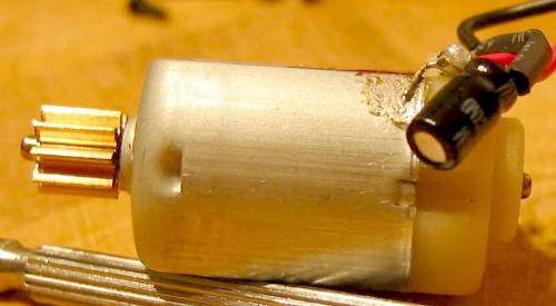
Would you look at that the exact same size! You just need to pry off the plastic gear from the front of the SB motor and pry out the end-bell holding tabs to continue (see picture below)
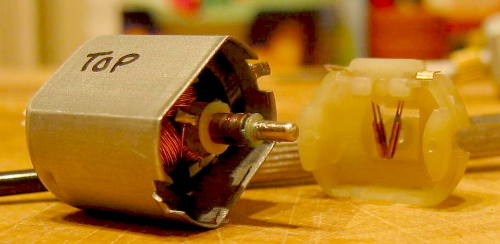
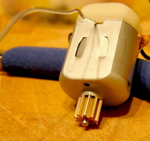
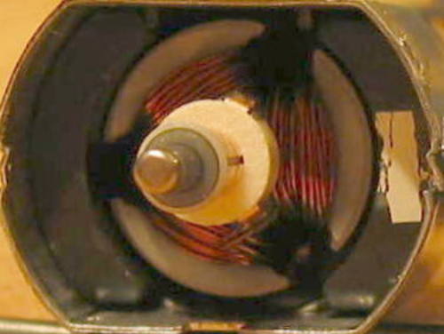
OK do you see those 'Tabs' sticking out from the motor case (can) these need to be flipped up before you can remove the end-bell from the motor. Note the cheap brush's on the end-bell of the Spinbrush motor. the SB armature should slide right out of the 'Can' and you'll be looking at the Isotropic Ferrite Magnets.
Isotropic Ferrite Magnets are about twice as strong as the stock magnets in the Stage 2 motor so the swap will add tons of torque to your lousy motor. Note the hold down spring, its the 'U' shaped piece on the bottom, remove this and remove the magnets slowly make sure to mark one of them so you won't mix them up. I used whiteout on the magnet to mark it. Remember it doesn't matter how you do it just make sure the magnets get oriented into the Stage 2 motor the same way you took them out of the SB motor. Once the magnets are removed put them aside.
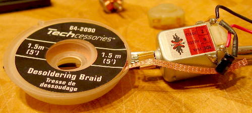
I've found the best way to remove the solder from the end-bell capacitors is to use Desoldering braid it's sold at Radio Shack so it should be easy to find.
The part number is 64-2090
Here you can see all the solder has been removed, to use the desoldering braid you simply place it over the solder and then place the soldering iron over the braid and wait until you see the solder being drawn up into the braid, move to a new section of braid and repeat until all the solder is gone. Sometimes you need to heat the wire and pry it up while still hot as even little bit of solder that remains does a good job of holding it down.
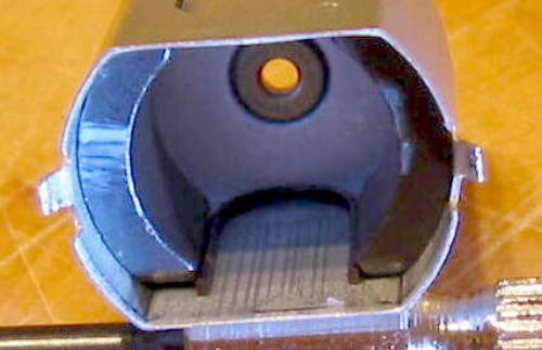
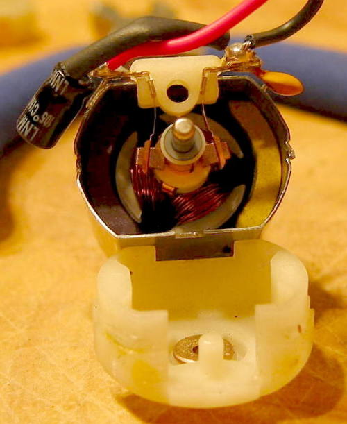
You need to pry out the end-bell holding tabs, then carefully insert a paper clip into the area shown in the photo to help pry the end-bell away from the 'Can' you can proceed 2 different ways here.
- You can keep pulling at the end-bell and try to push the brush's away from the armature using the paper clip.
- If you look carefully at the other side of the end-bell where the wires are soldered on you will see a small indentation where you can pry the brush's away from the end-bell and remove easily later.
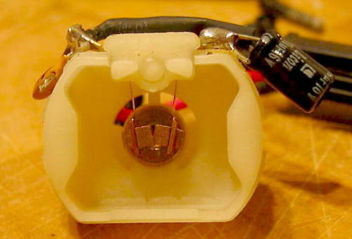
If you followed the 2nd method from the last step you will see the end-bell separate and the brush's will remain on the armature as in this photo. This is the best method as it ensures no force is applied to the brush's and the brush hold down springs as these are very fragile and are easily damaged
Here is what the end-bell and brush's look like when assembled, note the very square look of the brush's, this motor is a virgin so the brush's have not worn down to the shape of the armature. I have seen many sites telling everyone to use the 'water drip' method to break in the brush's, while the method works it's more of a pain and requires dismantling the motor to clean out any water residue. I use an easier method which will be outlined in the last step below.
Now you have to repeat the steps used to remove the magnets from the SB motor on your Stage 2 motor, the only difference will be that the armature will be in the way, you have to be more careful as you could damage something. It should be fairly easy, the only hard part is getting at the retaining spring. Once that has been removed you simply shake the magnets out. Hold the 'Can' firmly in one hand and throw you arm like you would throw a fastball but make sure the end on the 'Can' is exposed, the centrifugal forces will make the magnets fly out, make sure you don't knock someone out with flying magnets.
Insert the SB magnets into the Stage 2 'Can' remember to make sure the orientation is the same from the SB 'Can' to the Stage 2 'Can'. Insert the retaining clip and carefully slide it all the way back into place, don't use your fingers as the 'U' clip is sharp. The magnets should be sitting against the side walls of the 'Can', replace the end-bell without the brush's. Now check that the armature rotates freely, if not double check the position of the magnets and repeat until it moves freely. Now you can add the brush's and carefully replace the end-bell. Solder the capacitors to the outside of the 'Can' and test your work!

To test the motor I loosely attached some wires to the SB casing and touched them to the now completed Stage 2 motor, it should spin up nicely with the provided 3 volts. Break-in the brush's by running the motor for 15 minutes on the bench with no load, this should wear and polish the brush's to the shape of the armature. This should result in more energy getting to the motor through a wider contact area and will translate into better start-up and higher RPM. Put your Xmod together and give it a test run, you should see a big improvement on take-off and a slight improvement on your top speed.
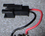
The first time I powered up I discovered the controls were backwards! The car went Backward when I wanted Forward and of course went Forward when I wanted to go backward. I'm not entirely sure if I rotated the magnets it would fix the problem so I went for the easiest solution which was to flip the connector wires on the motor, this means you end up with the black wire leading to a red wire on the motor and the red wire leading to black wire on the motor.
This can be done quite easy by pushing a paper clip into the small indention above the wire connector and gently pulling on the wires until they come out (do not use excessive force just wiggle and keep trying) once you have them both out reverse them and re-insert them back into the connector (see pictures below). Only reverse the polarity on the Connector that is attached to the motor otherwise when you change to a different motor it will run backwards.
 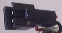
You can't see the inside but I'm sure you'll figure it out!
Update Jan 16th 2006
I have discovered that it does indeed make a difference which way you insert the magnets and that simply reversing the wires gets you moving in the correct direction you are reducing the amount of power the motor will make as the motor was designed to rotate a certain direction when power is applied the best solution is to re-open the can mark the magnets and swap the magnet position and test again. If that fails rotate each magnet 180 degrees and try again I admit with the isotropic magnets the change is not as noticeable as when you make this error with the Neodymium Magnets!
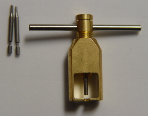
I added the photo of what a pinion puller looks like for these type of motors they sell for around $20-30 U.S. and if you intend on switching pinions it's a must have.
 |
|